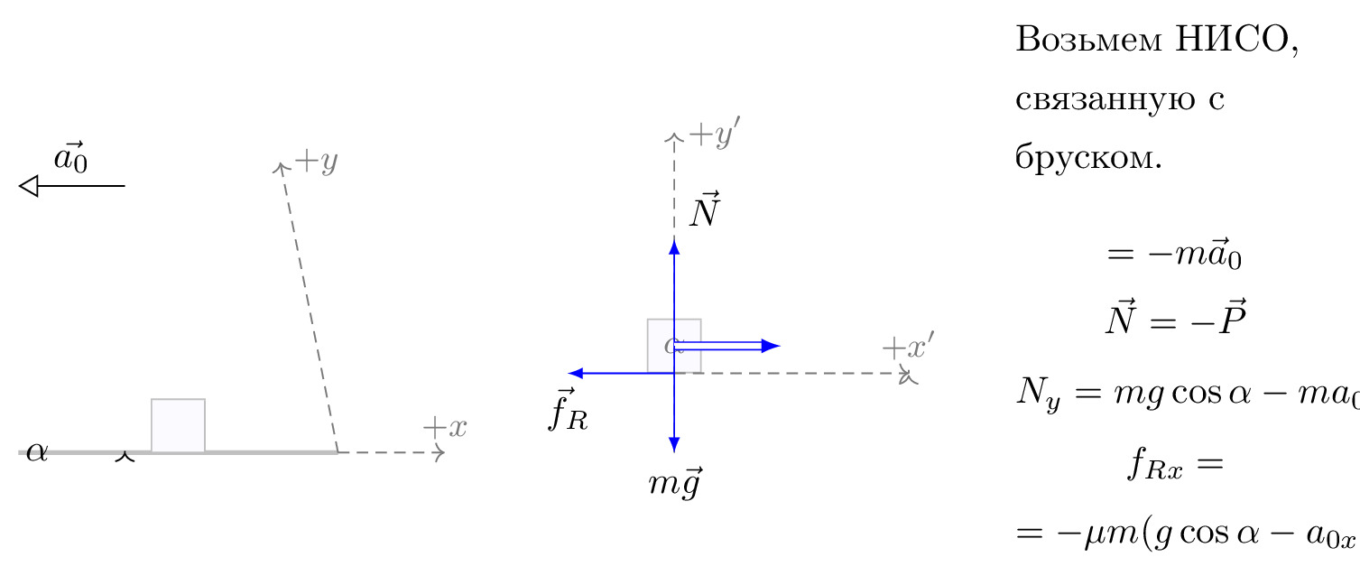
\documentclass[tikz]{standalone}\input{pre.tex}\begin{document}\begin{tikzpicture}[
    axis/.style={densely dashed,black!60,font=\small},
    force/.style={>=latex,draw=blue,fill=blue},
    % m/.style={rectangle,draw,fill=lightgray,minimum size=0.5cm,thin},
    m/.style={draw=black!30, rectangle,draw,thin, fill=blue!2, minimum size=0.5cm},
    m/.style={draw=black!30, rectangle,draw,thin, fill=blue!2, minimum size=0.5cm},
    interface/.style={draw=gray!60,
        postaction={draw=gray!60,decorate,decoration={border,angle=-135,
                    amplitude=0.3cm,segment length=2mm}}},
    plane/.style={draw=black!30, very thick, fill=blue!5},
    string/.style={draw=black, thick},
    pulley/.style={thick},
]

\matrix[column sep=0.5cm] {

    \begin{scope}[]
        \draw[->,>=open triangle 60] (1,1.5) -- node[above,pos=0.5] {$\vec{a_0}$} (0,1.5);
        %% Sketch
        \draw[plane] (0,-1) coordinate (base)
                         -- coordinate[pos=0.5] (mid) ++(\iangle:3) coordinate (top)
                         |- coordinate (d) (base) -- cycle;
        \path (mid) node[m,rotate=\iangle,yshift=0.25cm] (m) {};
        % \draw[pulley] (top) -- ++(\iangle:0.25) circle (0.25cm)
                       % ++ (90-\iangle:0.5) coordinate (pulley);
        % \draw[string] (m.east) -- ++(\iangle:1.5cm) arc (90+\iangle:0:0.25)
                      % -- ++(0,-1) node[m] {};

        \draw[->] (base)++(\arcr,0) arc (0:\iangle:\arcr);
        \path (base)++(\iangle*0.5:\arcr+5pt) node {$\alpha$};

        {[axis,->]
            \draw (d) -- (35:3) node[right] {$+y$};
            \draw (d) -- ++(1,0) node[above] {$+x$};
            % Indicate angle. The code is a bit awkward.
        }
    \end{scope}
&
    \begin{scope}[rotate=\iangle]
        \node[m,transform shape] (m) {};
        % Draw axes and help lines

        {[axis,->]
            \draw (0,-1) -- (0,2) node[right] {$+y'$};
            \draw (m.south) -- ++(2.2,0) node[above] {$+x'$};
            % Indicate angle. The code is a bit awkward.

            \draw[solid,shorten >=0.5pt] (\down-\iangle:\arcr)
                arc(\down-\iangle:\down:\arcr);
            \node at (\down-0.5*\iangle:1.3*\arcr) {$\alpha$};
        }

        % Forces
        {[force,->]
            % Assuming that Mg = 1. The normal force will therefore be cos(alpha)
            \draw (m.center) -- ++(0,{cos(\iangle)}) node[above right] {$\vec{N}$};
            \draw (m.south) -- ++(-1,0) node[below, pos=1] {$\vec{f}_R$};
            % \draw (m.east) -- ++(1,0) node[above] {$T$};
        }

    \end{scope}
    \draw[force,double equal sign distance=2pt,->] (m.center) -- ++(1,0) node[below, pos=1.5] {$\FIN$};
    % Draw gravity force. The code is put outside the rotated
    % scope for simplicity. No need to do any angle calculations.
    \draw[force,->] (m.center) -- ++(0,-1) node[below] {$m\vec{g}$};
&
\node[draw=none,text width=3cm, line width=0mm] at (0,0.5) {
Возьмем НИСО, связанную с бруском.
\begin{gather}
    \nonumber \FIN=-m\vec{a}_0\\
    \nonumber \vec{N}=-\vec{P}\\
    \nonumber N_y={}mg\cos\alpha-ma_{0x}\sin\alpha\\
    \nonumber f_{Rx}=\\
    \nonumber = -\mu{}m(g\cos\alpha-a_{0x}\sin\alpha)
\end{gather}
};
\\
};

\end{tikzpicture}\end{document}
