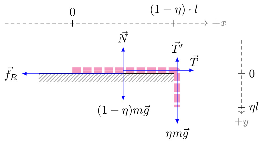
\documentclass[tikz]{standalone}\input{pre.tex}\begin{document}\begin{tikzpicture}[
    force/.style={>=latex,draw=blue,fill=blue},
    % axis/.style={densely dashed,gray,font=\small},
    axis/.style={densely dashed,black!60,font=\small},
    interface/.style={
        pattern = north east lines,
        draw    = none,
        pattern color=gray!60,
    },
    cargo/.style={
        rectangle,
        fill=magenta!40,
        draw=black!50,
        inner sep=2.5mm,
    },
    spring/.style={
        decoration={
            aspect=0.3,
            segment length=.8mm,
            amplitude=2mm,
            coil},
        decorate,
        draw=magenta!25
    },
    interface1/.style={draw=gray!60,
        % The border decoration is a path replacing decorator.
        % For the interface style we want to draw the original path.
        % The postaction option is therefore used to ensure that the
        % border decoration is drawn *after* the original path.
        postaction={draw=gray!60,decorate,decoration={border,angle=-135,
                    amplitude=0.3cm,segment length=2mm}}},
]
\def\angle{41}
%%%%%%%%%%%%%%%%%%%%%%%%%%%%%%%%%%%%%%
    \draw[thick, interface] (0,0) rectangle ++(4,-0.25);
    \draw[thick] (0,0) -- ++(4,-0);

    \draw[magenta!50,line join=round,line width=5pt,dash pattern={on 7pt off 2pt on 7pt off 2pt}] (1,2.85pt) -- ++(3,0) -- ++ (2.5pt,0) -- ++(0,-1.1);


    % \draw[black!10] (4,0) -- ++(0,1);
    \begin{scope}[yshift=0.5cm]
        \draw[axis,->] (-1,1) -- (5,1)
                        node [right] {$+x$};
        \draw[black] (1,0.9) -- ++(0,0.2) node[above] {$0$};
        \draw[black] (4,0.9) -- ++(0,0.2) node[above] {$(1-\eta)\cdot l$};
    \end{scope}

    \draw[axis,->] (6,1) -- ++(0,-2.2)
                    node [below] {$+y$};

    \draw[black] (5.9,0) -- ++(0.2,0) node[right] {$0$};
    \draw[black] (5.9,-1) -- ++(0.2,0) node[right] {$\eta l$};

    \draw[force,->] (2.5,0) -- ++(-3,0) node[left] {$\vec{f}_R$};
    \draw[force,->] (2.5,0) -- ++(0,-0.8) node[below] {$(1-\eta)m\vec{g}$};
    \draw[force,->] (2.5,0) -- ++(0,0.8) node[above] {$\vec{N}$};

    \draw[force,->] (4.1,-0.5) -- ++(0,1) node[above] {$\vec{T}'$};
    \draw[force,->] (4.1,-0.5) -- ++(0,-1) node[below] {$\eta m \vec{g}$};
    \draw[force,->] (2.5,0.1) -- (4.6,0.1) node[above] {$\vec{T}$};

    % \draw[axis] (4,0) -- ++(1,0);
    % \draw[axis] (4,-1) -- ++(1,0) ;
    % \draw[axis,<->] (5,0) -- node[right,black] {$\eta l, m_2=\eta m$} (5,-1);


\end{tikzpicture}\end{document}
