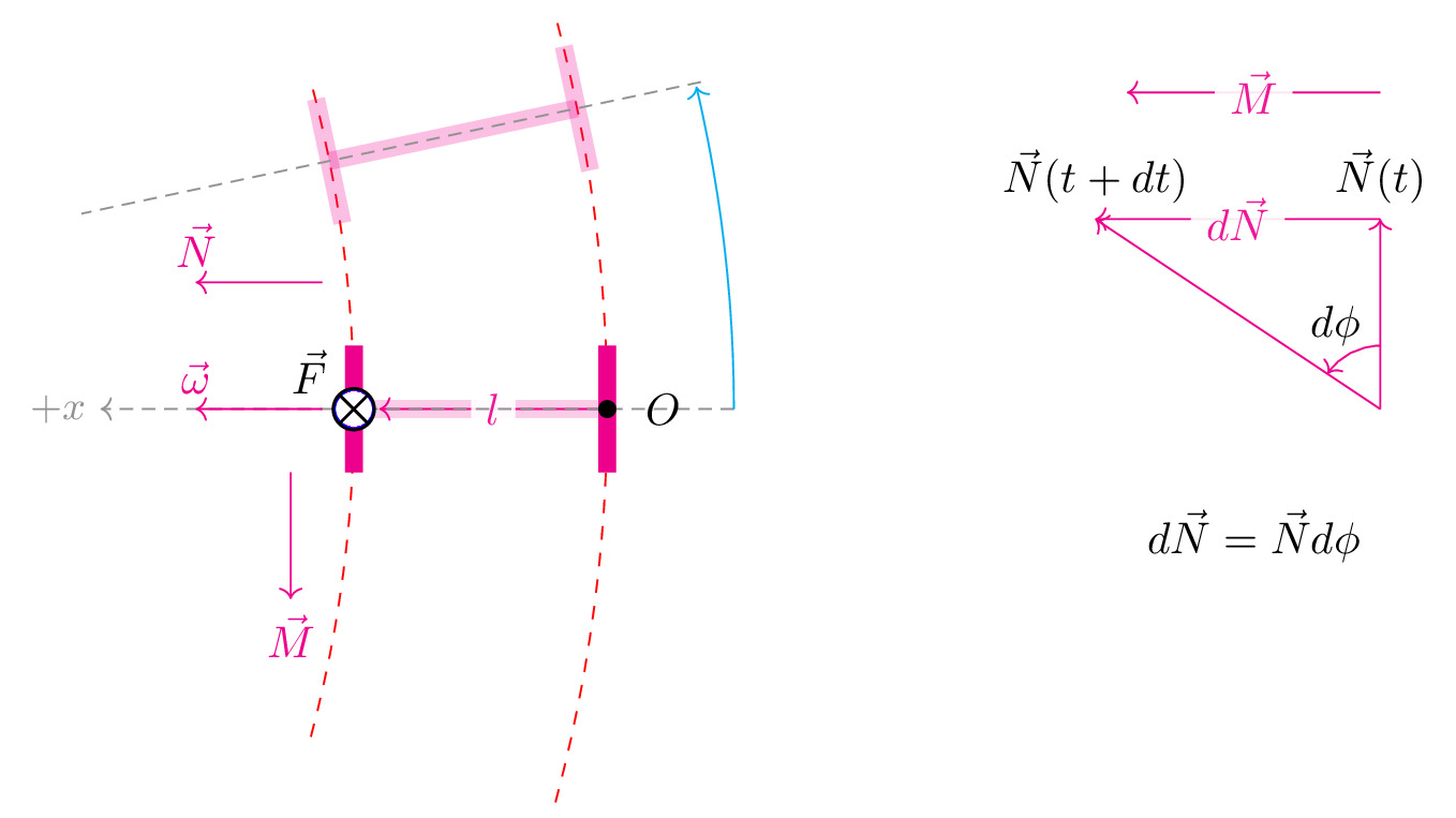
\documentclass[tikz]{standalone}\input{pre.tex}\begin{document}\begin{tikzpicture}
\matrix[column sep=2cm] {

    % \draw[interface] (-0.5,1) rectangle (-0.1,1.5) (0.1,1.5) rectangle (0.5,1);

    % \draw[interface] (-0.5,-1) rectangle (-0.1,-1.5) (0.1,-1.5) rectangle (0.5,-1);

    % \draw[axis,magenta] (0,-1.5) -- (0,1.5);
    % \draw[magenta,->]
    %   (0,1.75) -- ++(0,0.5)
    %   node[above] {$\vec\omega$};
    % \draw[magenta,->] (0.5,1.75) -- ++ (0,0.5)
    %   node[above] {$\vec{N}$}
    %   ;

    % \draw[fill=magenta, magenta] (-0.5,-0.15) rectangle (0.5,0.15);

    % \fill[magenta] (0,-1.25) coordinate (1) circle (2pt) node[below, yshift=-0.5em] {$O$};

    % \fill[magenta] (0,1.25) coordinate (2) circle (2pt);

    % \draw[->, thick, blue] (1) -- node[caption] {$\vec{l}$} (2);
    % \draw[->, thick, magenta] (2)++(-1,0) -- node[caption] {$\vec{M}$} ++(-2,0);

    % \draw[fill=white, draw=blue] (0,1.25) circle (4.3pt) node {$\bigodot$} node[right, xshift=0.5em] {$\vec{F}$};
 %    \draw[axis] (-0.6,-3) arc (-20:20:10);
    \draw [red,dashed,domain=-15:15] plot ({10*cos(\x)-10}, {10*sin(\x)});
    \draw [red,dashed,domain=-15:15] plot ({12*cos(\x)-10}, {12*sin(\x)});

    \draw[line width=4pt, magenta ,opacity=0.2] (0,0) -- (2,0);
    \draw[magenta,->] (2,0) -- node[caption] {$l$} (0.2,0);
    \draw[line width=4pt, magenta] (0,-0.5) -- (0,0.5);
    \draw[line width=4pt, magenta] (2,-0.5) -- (2,0.5);

    \begin{scope}[yshift=2cm, rotate=12, xshift=-2mm]
        \draw[opacity=0.25, line width=4pt, magenta] (0,0) -- (2,0);
        \draw[opacity=0.25, line width=4pt, magenta] (0,-0.5) -- (0,0.5);
        \draw[opacity=0.25, line width=4pt, magenta] (2,-0.5) -- (2,0.5);
        \draw[axis] (3,0) -- (-2,0);
    \end{scope}

    \draw[axis,->] (3,0) -- (-2,0) node[left] {$+x$};

    \draw [cyan,->,domain=0:12.25] plot ({13*cos(\x)-10}, {12*sin(\x)});

    \draw[magenta,->]
        (-0.25,0) -- ++(-1,0)
        node[above] {$\vec\omega$};
    \draw[magenta,->, yshift=1cm]
        (-0.25,0) -- ++(-1,0)
        node[above] {$\vec{N}$};

    \draw[magenta,->]
        (-0.5,-0.5) -- ++(0,-1)
        node[below] {$\vec{M}$};
    \draw[fill=white, draw=blue] (0,0) circle (4.3pt) node {$\bigotimes$} node[left, above, xshift=-1em] {$\vec{F}$};

    \fill[black] (2,0) coordinate (1) circle (2pt) node[right, xshift=0.5em] {$O$};
    &
    \begin{scope}
    \draw[magenta,->]   (0,0) coordinate (o) -- ++ (0,1.5) coordinate (i)
        node[above, black] {$\vec{N}(t)$};

    \draw[magenta,->]   (0,0) -- ++ (-2.25,1.5) coordinate (ii)
        node[above, black] {$\vec{N}(t+dt)$};

    \draw[magenta,->] (i) --node[caption] {$d\vec{N}$} (ii);

    \draw[magenta,->] (i)++(0,1) --node[caption] {$\vec{M}$} ++(-2,0);

    \draw pic["$d\phi$",draw=magenta,->,angle eccentricity=1.5,angle radius=0.5cm] {angle=i--o--ii};

    \draw (-1,-1) node {$d\vec{N}=\vec{N}d\phi$};
    \end{scope}
    \\
};


\end{tikzpicture}\end{document}
